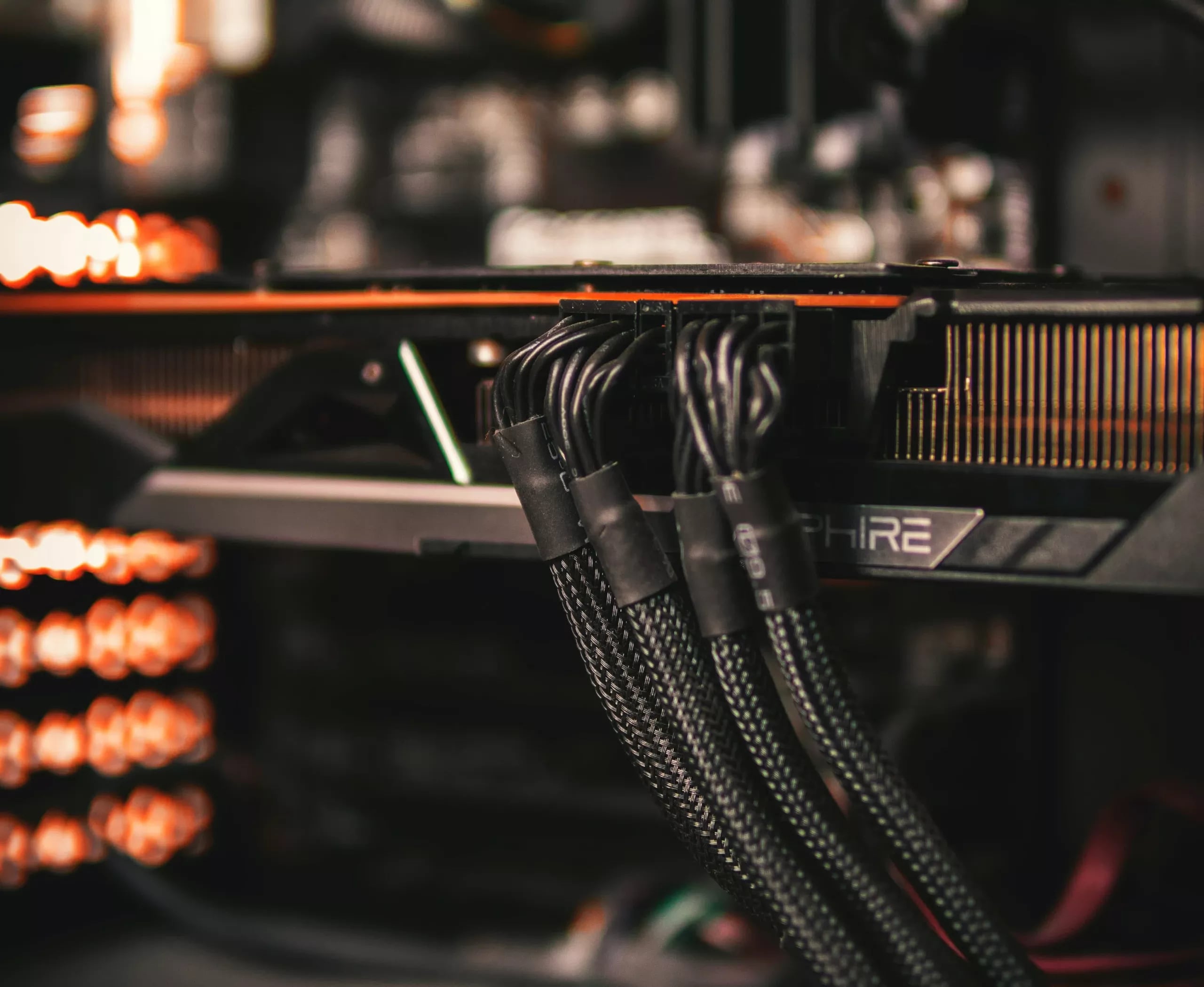
Put a hand on the 16-pin plug where it meets the card, ten minutes into something demanding. It is warm. Now slide your fingers back along the sleeve and feel the individual wires. If one or two of them are noticeably warmer than the rest, you have just measured, with the crudest instrument available, the only thing about this connector that actually matters.
A warm plug is not a fault. Fifty amps through a housing the size of a thumbnail is going to be warm. One wire warmer than its neighbours is a different statement entirely, and the rest of this piece is about why that difference exists, why the card cannot see it, and what the useful response is.
The arithmetic printed on the box
Six hundred watts at twelve volts is fifty amps. The connector carries it on six 12 V pins, so a plug that shared perfectly would put 8.3 A down each one.
The terminal's own published figure is a minimum of 9.2 A per contact, measured with all twelve contacts energised and a ceiling of 30 K rise over ambient. Divide one by the other and you have the design margin of the whole standard: about ten per cent.
Hold that against what it replaced. The eight-pin PCIe plug carries 150 W over three 12 V pins — 12.5 A split three ways, 4.2 A a pin, on terminals whose published rating sits in the same nine-amp neighbourhood. Its margin is a factor of two.
So the new connector did not arrive with worse terminals. It arrived with a comparable terminal and roughly half the pins per amp, and the headroom fell from about two to about one-and-a-tenth. Every consequence below is that one number working itself out.
Why six pins never share
Six pins wired in parallel are six resistors in parallel, and current divides between them in proportion to conductance. Halve a path's resistance and it takes twice the current. Nothing in the plug decides the split; the split is simply what the resistances produce.
So it is worth knowing what a path is made of. Sixteen-gauge copper runs about 13 mΩ per metre, which makes a 600 mm conductor roughly 8 mΩ. A clean, fully seated terminal pair adds a few milliohms on top. A worn, oxidised or half-seated one adds tens.
That is the whole problem in one line: the part of the path that varies is the same size as or larger than the part that does not. The wire is a fixed cost. The contact decides the outcome. A beautifully made cable seated indifferently will behave worse than a plain cable pushed properly home.
Put numbers on it. If all six paths sit at 12 mΩ, each carries its 8.3 A and nothing interesting happens. Now let one contact settle unusually well at 6 mΩ while the other five drift out to 20 mΩ — a three-to-one spread, well inside what ordinary wear produces:
- the good path takes 40 per cent of the total: 20 A
- each of the other five takes 12 per cent: 6 A
Twenty amps on a nine-amp terminal, and not one component in that example is defective. A three-to-one resistance spread — which you cannot see, cannot hear and have no way to measure without cutting into the cable — is enough to put a single pin at more than double its rating.
Why it does not simply run away every time
Copper's resistance rises about 0.39 per cent per kelvin, so a hot pin becomes slightly more resistive and sheds a little current back to its neighbours. That is a brake, and it is why the great majority of unbalanced plugs just run warm for years and never do anything else.
The accelerator is mechanical rather than electrical. Somewhere above 100 °C the housing softens, the contact spring loses preload, and the mating area starts to shrink. Once the plug is losing contact area, resistance climbs faster than the temperature coefficient can push current away, and that pin is on its own. The failure is not gradual heating; it is a brake that works fine until the geometry stops holding still.
What was actually measured
The clearest public measurement came from der8auer, who put a clamp meter on the individual conductors of a 5090 Founders Edition under load and a thermal camera on the plug. Two of the six live wires were carrying almost nothing, one about 2 A, one about 5 A, one about 11 A, and the last over 22 A. The connector at the power-supply end reached about 150 °C.
Reduce that to the two figures that travel: the median wire was carrying somewhere near 5 A while the worst carried 22. The hot pin took more than four times the median, about two and a half times the even share, and roughly 2.4 times the terminal's own rating.
Which is the point of the arithmetic above. Nobody needs to posit a counterfeit cable or a manufacturing defect to arrive at those amps. A three-to-one spread in contact resistance produces them on its own, and a three-to-one spread is an ordinary outcome of plugging a connector in a few times.
It is also not rare. Owners of boards that report current per pin routinely see individual pins above 10 A on machines that are working perfectly. Imbalance is the normal condition of this connector. Catastrophe is the rare tail of it.
Why the card does not stop it
A graphics card measures its input current across shunt resistors, and how many it has decides what it is able to know.
The 3090 Ti split the six 12 V wires across three shunts feeding separate phase banks. A card wired that way can see one pair going quiet, and it can act. The 40- and 50-series reference designs merged that arrangement, and on the 5090 Founders Edition all six wires arrive at one shunt — a single node, one number.
The consequence is exact. Fifty amps arriving as 8+8+8+8+8+10 and fifty amps arriving as 2+2+5+6+13+22 are the same reading. Not a reading the card ignores — a reading it cannot form. Five of the six wires could fall off and the card would carry on drawing its target power down the sixth, reporting nothing unusual, because nothing unusual is visible from where it is looking.
The exception proves it. ASUS put current sensing back on the individual pins of its Astral boards and raised an alert when they diverge, and sold that as a feature. It is a feature. That is the uncomfortable part.
The plastic is not what protects you. Telemetry is, and on most cards there is none.
Where the first generation of failures came from
The 4090's melted plugs were mostly a different fault with the same arithmetic behind it. Igor's Lab took the four-to-one adapter apart and found the four thick leads split onto six pins over solder bridges roughly 0.2 mm thick and 2 mm wide, soldered inconsistently between samples. A bridge like that can crack when the cable is bent — and a cracked bridge is not an open circuit, it is a high-resistance path, which is the input the model above turns into somebody else's twenty amps.
Gamers Nexus and others found the second contributor by examining failed units: partial insertion. A plug that is not fully home makes contact near the tip of the terminal, on a fraction of the intended area, which is the same defect arriving by a different road.
Then the cure became the fault. CableMod's angled adapters — bought specifically to take bending out of the equation — were recalled after the male connector could work loose and melt into the card.
The standards body's answer was the 12V-2×6 revision: the four sense pins were shortened so that a plug which is not fully seated cannot be granted full power, and the power terminals were lengthened a little to make contact earlier. That is a real fix for a real cause, and it should be said plainly that seating-related failures are the ones it removes. It does nothing about balance. Six parallel paths still divide fifty amps by their resistances, exactly as before.
Why it has not happened to you
It probably will not. When several outlets tried to reproduce the melting deliberately — different supplies, different cables, native and adapted — they largely failed to make a healthy, properly seated cable fail. NVIDIA's own count of first-generation incidents ran to dozens against a shipped base in the hundreds of thousands.
Both halves of that are true at once, and this connector has generated two bad genres of writing by keeping only one of them. It is not a scandal that every card is about to burn. It is not user error that a connector with ten per cent of design margin and no per-pin visibility produces a tail of failures when its contacts wear. It is a low-probability event with a completely understood mechanism, riding on a standard that left no room for the mechanism to happen in.
What to actually do
- Use the cable that came with the supply, into a native 12V-2×6 socket. Every adapter is another pair of terminals, and every pair of terminals is another chance at a spread.
- Seat it until it clicks, then look at it end-on. No gold showing. This is the single highest-value check on the list, because seating is the cause the revision was written to kill.
- Start any bend at least 35 mm from the plug body. A bend at the shell levers the terminals off their seats — it changes contact area, which is the quantity that matters.
- Count mating cycles. The terminals are rated for roughly 30 insertions. A cable that has been through three builds is a used part, and it is the cheapest part in the machine to replace.
- Feel the wires once a month under load. Even warmth across all six is the connector working. One wire warmer than its neighbours is an uneven split, and the correct response is a new cable, not an investigation.
- If your board reports per-pin current, turn the alert on. If it does not, the check above is the only instrument you have.
Two things we would not buy
An angled adapter bought to solve a bend. The vendor with the most popular one recalled it after those adapters melted into cards, and the failure mode was precisely the one the part was sold to prevent.
And a 500-watt-class card fed through a four-to-one adapter from a supply built before this connector existed. That adapter is where the entire first generation of documented failures began. If the supply has no native socket, replace the supply rather than adapting the cable — it is the cheaper half of the decision, and this is the one place in a build where "it has been fine so far" carries no information at all. The failure has no warning you have not been told to feel for.
How this was put together
Six independent sources sit under the numbers above: der8auer's clamp-meter and thermal-camera session on a 5090 Founders Edition; Buildzoid's board-level reading of the shunt arrangement across the 3090 Ti, 4090 and 5090; Igor's Lab's teardown of the original four-to-one adapter; the connector datasheet's own 9.2 A minimum per contact; the PCI-SIG revision that shortened the sense pins; and the reproduction attempts by several outlets that failed to make good cables fail, alongside what owners of per-pin telemetry report seeing day to day.
The derived figures are ours: the 8.3 A even share, the ten-per-cent margin against the eight-pin's factor of two, and the worked three-to-one resistance spread that lands a single pin at 20 A without a defective component anywhere in it.