Put a thermal camera on a working machine and the board is mostly cool. One strip is not: the row of components between the processor socket and the top edge, under the finned block that most boards now put there. Under a sustained all-core load it will be the hottest thing on the board, and on a bad board in a still case it will be hotter than the processor's own package.
That strip is the voltage regulator, and its temperature is not a defect. It is the by-product of the single hardest electrical job in the machine.
What the processor actually asks for
The power supply delivers 12 volts. The processor runs its cores at somewhere around 1.2 volts, and it wants that voltage held steady while its draw changes by tens of amps in microseconds.
Start with the current, because everything follows from it. A processor pulling 200 W at 1.2 V is drawing:
200 ÷ 1.2 = 167 amps.
That is not a computing number, it is a welding number. It arrives on the 12 V rail as a manageable 17 A or so, and something on the board has to turn it into 167 A at a tenth of the voltage without letting the voltage sag when a core wakes up. The thing that does it is a buck converter, and the strip above the socket is where it lives.
Why it is many small converters instead of one
Each phase is the same handful of parts: a pair of transistors that alternately connect an inductor to 12 V and to ground, that inductor, and the capacitors that smooth what comes out. A controller runs them all and they share one output node — the processor.
Splitting the job has two payoffs, and the first one is the reason the strip is survivable at all.
Conduction loss in a switching converter goes as the square of the current. Put all 167 A through one phase and the loss is proportional to 167²; split it across eight phases and each carries 21 A, so each dissipates something proportional to 21², and eight of those together come to one eighth of the single-phase figure. Dividing the current by eight divides the heat by eight — and, just as importantly, spreads what remains across eight separate places on the board instead of concentrating it in one.
The second payoff is smoothness. The controller staggers the phases so they take turns rather than firing together. Eight phases at 45-degree intervals means the ripple each one produces is partly cancelled by its neighbours, so the voltage the processor sees is steadier and needs less capacitance to clean up.
That staggering is also the literal answer to the headline. The phases are handing the load to each other, thousands of times a second, in the order the controller sets — and the heat appears along the whole row because every one of them is taking its turn.
Why the strip sits where it sits
The regulator could in principle be anywhere on the board. It is always crammed between the socket and the power connector, and the reason is that 167 A number again.
A copper trace carrying 167 A dissipates I²R watts. Work out what a single milliohm of resistance costs on that path:
167² × 0.001 = 28 watts.
Twenty-eight watts thrown away in a piece of copper, for one thousandth of an ohm. That is why the output side of the regulator is not really wired at all — it is poured, as wide planes through the board's inner layers, over the shortest distance the layout allows. Every extra centimetre between a phase and the socket is measured in watts, so the phases go as close to the socket as the socket's own keep-out area permits, which puts them exactly where you find them.
The three ways the strip makes heat
Conduction
Current through the transistors' on-resistance and through the inductor's winding resistance. This is the part that scales with the square of the current and dominates under heavy sustained load.
Switching
Every time a transistor turns on or off, it spends a moment partly conducting — a moment with both voltage across it and current through it. Multiply that by the switching frequency and you have a loss that scales with how often the converter switches rather than with how hard it is working. It is why a regulator can be warm at idle.
The magnetics
The inductor's core loses energy to the alternating field, and the winding loses more to its own resistance. Inductors run hot; on many boards they are the hottest individual components in the strip, and the heatsink above them is often not touching them at all.
These three pull against each other. Switching faster shrinks the ripple and lets the designer use smaller inductors — and raises the switching loss. Switching slower cuts that loss and demands bigger magnetics and more capacitance. The frequency a board picks is a judgement about which heat it would rather have.
The load step is the hard part, not the steady state
Everything above describes the converter under a constant load, which is the easy case. The difficulty is that a processor’s draw is not constant — it can go from twenty amps to a hundred and fifty in a few microseconds when the cores come out of an idle state together.
The converter cannot respond that fast. Its phases switch at a few hundred kilohertz, so the soonest any of them can react is a handful of microseconds away, and in the meantime something has to supply that current or the voltage collapses. That something is the bank of capacitors around the socket, which is why they are there and why their arrangement is as considered as the phases themselves.
Two design consequences follow. A higher switching frequency shortens the gap the capacitors have to bridge — bought, as always, with more switching loss. And more phases means more of them are mid-cycle at any moment, so the collective response to a step is quicker than the same current handled by fewer, larger phases.
You also meet the deliberate side of this as a setting. The voltage is allowed to sag slightly under load on purpose, and boards expose how aggressively to fight that sag. Set the compensation too hard and the machine overshoots when the load drops away, which is harder on the parts than the sag ever was. A board that holds voltage perfectly flat under a load step is not obviously the better board; it is a board making a different trade.
What the phase count on the box is not telling you
Board marketing counts phases the way processors used to count megahertz, and the count on its own tells you very little.
Some boards run true independent phases with one control channel each. Others use doublers, where one control channel drives two sets of power stages — closer to eight-and-a-half phases than sixteen, and with a slower response to a load step. Others simply wire two power stages to one channel in parallel, which shares the current but does nothing for the ripple. A board advertising sixteen may have any of these arrangements behind the number.
Meanwhile the thing that most often decides the temperature is the least advertised: the heatsink. Its mass, its fin area, whether the thermal pad actually contacts the inductors as well as the power stages, and whether any air in the case moves across it at all. Two boards with identical phase counts and different blocks are not comparable, and the only way to know is a review that measured the strip under a sustained load rather than counting the parts.
When this matters, and when it does not
It would be dishonest to make this sound like a crisis. For a mid-range processor at stock settings, in a case with any airflow, essentially every current board's regulator is comfortable and you will never think about it.
It starts to matter in four situations, and they are specific:
- Sustained all-core work — rendering, compiling, encoding. Gaming loads the processor in bursts; a two-hour render does not.
- A high-draw processor on an entry board. The gap between a board designed for 65 W parts and one designed for 250 W parts is real, and it is mostly in this strip.
- Overclocking, where the current goes up and the demand for a steady voltage goes up with it.
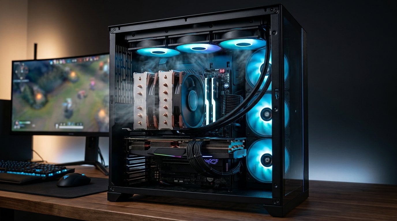
- Cases with no airflow over the board — which now includes a great many builds, because a large air cooler or a top-mounted radiator can leave the strip in still air.
Two things we would not buy
A board chosen on its phase count. The number is not comparable between vendors, it does not distinguish doubled from true phases, and it says nothing about the heatsink that actually sets the temperature.
And an expensive board bought for regulator headroom that a 65 W processor will never use. That money buys measurable improvement on a 250 W part under sustained load and buys a specification sheet on a modest one. If the processor is modest, spend the difference on memory or storage, where it will show up in something you can feel.
Reading a regulator temperature chart
Reviews that measure this publish one of two very different numbers, and the difference matters.
A thermal camera or a surface probe reads the heatsink, which is the outside of the problem. The power stages underneath are hotter than the block above them, and how much hotter depends on the thermal pad between them — a stage running twenty degrees above its own heatsink is unremarkable. So a chart showing a comfortable 70 degrees on the block is not telling you the components are at 70.
The components themselves derate as they warm: a power stage rated for a large current at 25 degrees is rated for considerably less at 100, and the datasheet curve, not the headline figure, is the honest specification. This is why a board can be stable in a benchmark and unstable in the third hour of a render — nothing failed, the parts simply moved down their own curve.
What to look for, then, is a review that loaded the board for twenty minutes or more and reported the plateau rather than the peak of a five-minute run, and ideally one that says where it put the probe.
What to do
- Read a review that put a probe on the strip under a long all-core load, not a gaming benchmark. Peak temperature after twenty minutes is the number that matters.
- Give it air. A slow fan moving anything at all across that corner is worth more than several phases. Tower coolers that blow across the board help by accident; many closed-loop layouts leave the corner dead.
- Match the board to the processor's sustained draw, not to its model name.
- If you overclock, watch the strip rather than the core. The processor will report its own temperature happily while the regulator behind it is the part that is actually running out of room.
How this was put together
The board-level reading comes from the people who trace these strips component by component: Buildzoid's teardown analyses of regulator topology, which is where the doubled-versus-true-phase distinction is actually settled; der8auer's thermal imaging of boards under sustained load; Igor's Lab's efficiency and temperature measurements across board tiers; and the sustained-load VRM temperature testing published by Hardware Unboxed and TechPowerUp in their board reviews. The derating behaviour of the power stages comes from the component datasheets themselves.
The derived figures are ours: the 167 amps a 200 W processor draws at 1.2 V, the eightfold cut in conduction loss that eight phases buy over one, and the 28 watts that a single milliohm of resistance would burn on that output path — which is the number that explains why the strip is where it is rather than anywhere more convenient.